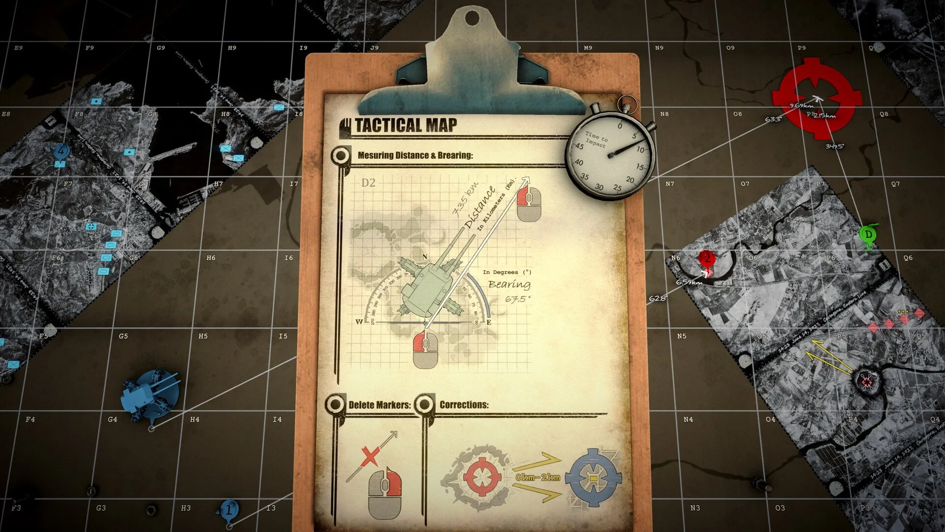
Triangulation in Iron Nest is the process of combining two incomplete spotter reports to find one target location. A bearing only tells you which direction the target is from an observer, while a distance only tells you how far away it is. Plot both reports on the tactical map, and the point where they overlap reveals where the target is located.
For two bearing reports, place each spotter at the correct map position, use the yellow pencil to draw outward along the supplied bearing, and extend both lines until they cross. You can then mark that intersection and measure a new bearing and distance from the Iron Nest for your firing solution.
Jump To Section:
How Triangulation Works
Plot the Spotters
Draw the Bearing Lines
Find the Intersection
Why the Lines Do Not Meet
Using Distance Reports
Handling Multiple Locations
Create the Firing Solution
How Triangulation Works in Iron Nest
A single spotter bearing cannot identify an exact target because the enemy could be anywhere along that direction. The bearing creates a line of possible locations beginning at the observer and continuing across the map.
A second report removes most of that uncertainty. When another spotter observes the same target from a different position, its bearing creates another line. The enemy is located where those two lines intersect because that is the only point lying in both reported directions.
The spotters are only used to discover the target position. Once you have marked that position, you still need to measure from the Iron Nest itself before entering the final values into the firing system.
Plot Both Spotters at Their Reported Positions
Open the tactical map and identify the location of each spotter before drawing anything. Every bearing must begin at the observer who supplied it, so even a correctly angled line will be wrong if its starting position is misplaced.
Place or identify the first spotter using the location given in the report, then do the same for the second. Zoom in enough to avoid placing either observer in the neighboring grid or on the wrong side of a map subdivision.
Do not begin either observation line from the Iron Nest. The report describes where the target appears from the spotter’s position, not from your turret. Your own position becomes relevant only after the target has been located.
Draw Each Bearing With the Yellow Pencil
Select the yellow pencil and begin the first line directly on the first spotter. Move the line outward until its displayed bearing matches the number in the report.
The endpoint does not represent the target by itself. A bearing gives you an angle but no range, so continue the line far enough that it can cross the second observation. Extending it toward the edge of the map is easier than repeatedly guessing how long it needs to be.
Repeat the same process from the second spotter. Start on the observer’s exact position, match the second reported bearing, and extend the line across the likely target area.
Make sure both lines point away from their spotters in the direction of the reported bearing. A line can appear to have the correct angle while extending in the opposite direction, which places the potential target on the wrong side of the observer.
Mark Where the Two Bearing Lines Intersect
Once both lines are drawn correctly, follow them across the map until they meet. Their intersection is the triangulated target position.
Place a clear target mark at the crossing point rather than relying on the pencil lines alone. This gives you one stable location to measure from after you clear or reorganize the rest of the map.
If the lines create a tiny gap or cross at slightly different points because of imprecise placement, recheck the spotter locations and bearings before choosing the middle. Small errors at the observer can produce much larger errors by the time the line reaches a distant target.
When both reports are plotted accurately, the intersection should give you a far better target position than attempting to judge the location from terrain or direction alone.
Why the Triangulation Lines Do Not Meet
If the lines travel away from one another, the first thing to check is the position of each spotter. A bearing is only correct when it begins at the exact observer location used in the report.
Next, confirm that each line is extending in the correct direction. Drawing the same angle backward sends the line 180 degrees away from the target, which makes the two observations appear completely unrelated.
The lines may also be too short. Because the reports do not always include a target distance, the intersection could be much farther across the map than expected. Extend both bearings toward the map boundaries before deciding they are parallel.
If they still do not meet, erase the lines and plot them again in this order: spotter position first, line origin second, bearing third, and length last. Rebuilding the plot methodically is usually faster than trying to adjust two incorrect lines at once.
What if the Bearings Are Nearly Parallel?
Two similar bearings can intersect very far from the spotters. Even a small difference in angle eventually brings the lines together, but the crossing point may sit outside the portion of the map you are currently examining.
Extend both lines as far as the map allows and zoom out to follow their direction. Do not force an intersection near the observers simply because that is where you expected the target to be.
If the bearings are genuinely identical and begin from different locations, they remain parallel and cannot produce one target point. You will need another observation, a distance report, or reconnaissance before the position can be narrowed further.
How to Triangulate With Distance Reports
When a spotter supplies a distance instead of a bearing, use the compass rather than the yellow pencil. Place the center of the compass on the observer and open it to the reported distance.
This creates a circle around the spotter. The target could be anywhere along that circle because every point on its edge is the same distance from the observer.
If a second spotter also gives a distance, draw another circle around that observer. The target must be located where the two circles cross.
The same principle applies as bearing triangulation: each report produces a set of possible locations, and combining the reports reveals the points that satisfy both.
Using One Bearing and One Distance
Iron Nest can also give you different information from each observer. When one spotter reports a bearing and another provides a distance, draw a line from the first and a circle around the second.
The target lies where the bearing line touches or passes through the distance circle. This allows you to triangulate without needing two reports of the same type.
Keep both marks visible until you have confirmed the final location. Erasing the first report after drawing the second removes the reference needed to identify their overlap.
What to Do When You Get Two Possible Locations
Two distance circles can intersect twice, and a bearing line can pass through a distance circle at two different points. Both locations satisfy the supplied information, so the map cannot always determine which one contains the actual target.
Compare both points against the mission area, terrain, and any additional reports. One may sit in an impossible location while the other lines up with the expected enemy position.
When both remain believable, use reconnaissance to check them before spending several normal shells. Recon planes or STAR shells can reveal which intersection contains the target and prevent you from building an accurate firing solution for an empty location.
A third observation also resolves the uncertainty. Plot the additional bearing or distance and see which of the original points matches the new report.
Turn the Triangulated Point Into a Firing Solution
The spotter lines locate the target, but they are not the values used to aim your gun. After marking the correct intersection, begin a new measurement from the Iron Nest to the target.
Measure the target’s bearing and distance from your own position, then transfer the range into the ballistic calculation process. Use the resulting charge and elevation together with the measured bearing to prepare the shot.
This creates two separate map stages. The first begins from the spotters and discovers where the enemy is located. The second begins from the Iron Nest and determines how your turret must fire to reach it.
Mixing those stages is the most common reason an apparently correct triangulation still produces a bad shot. The spotter bearing finds the target; your turret bearing aims the weapon.
Correct the Shot Without Rebuilding Everything
After firing, use the impact information to determine whether the target mark or the firing solution needs adjustment. A shell landing close to the target usually means the triangulation was usable and only the shot requires correction.
Do not erase the original intersection after every near miss. Keep the target mark and adjust from the observed impact unless new intelligence shows that the enemy moved or the original reports were plotted incorrectly.
Recalculate the location only when the spotter positions were wrong, the bearings were reversed, or a later report identifies a different target position.
Common Iron Nest Triangulation Mistakes
The most damaging mistake is drawing every bearing from the Iron Nest instead of from the reporting spotters. This preserves the angles but shifts both lines to the wrong origins, creating an intersection that has no connection to the actual reports.
Another common problem is treating the end of a bearing line as the target. The line has no meaningful endpoint until another report intersects it, so extend it freely rather than trying to estimate the distance.
Distance reports create circles, not straight lines. Using the pencil for a distance removes every other possible direction and turns the report into information it never supplied.
Finally, do not assume two possible intersections mean the plotting failed. That is a normal result when the available observations cannot distinguish between both locations. Use terrain, reconnaissance, or another report to choose between them.
Iron Nest Triangulation Explained
To triangulate in Iron Nest, plot each spotter at the correct map position and draw the reported bearing outward from that observer with the yellow pencil. Extend both lines until they cross, then mark the intersection as the target.
When a report gives distance, use the compass to create a circle around the spotter. Combine that circle with another circle or bearing line and inspect the points where the two reports overlap.
Once the target is marked, measure a new bearing and range from the Iron Nest itself. Those final measurements belong to your firing solution, while the original spotter reports are only used to discover the target’s location.